A unique feature of gCADPlus landscape design software is its ability to apply transparency to filled entities such as circles, polylines, rectangles, polygons, etc. The figure below shows a detailed design for a food garden with a greenhouse in one corner of the plot. A block (symbol) with a buff color with a transparency value of less than 255 is used as a zone indicator and is shown overlaying the location of the greenhouse. This technique draws the viewer’s eye to that structure, but since transparency is applied to the circle, it is still possible to see the underlying path and planting despite the fill.
Tip: The linetype of the circle was set to a dot pattern and a line thickness of 0.8mm.
Click here to download a copy of the drawing.
This approach is also useful when there is a need to display lower canopy detail through the upper canopy. Here is an example. A symbol for an existing tree planted near a boundary overlies an area of interest so the designer has applied a transparency value of 50 to the filled polyline indicating the canopy. Understory detail is now clearly visible.
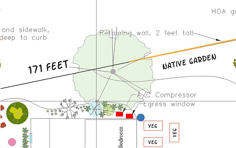
![]() Here we show that a block symbol containing a filled circle entity with a low value for transparency can be used with good effect to indicate zones within a landscape design.
Here we show that a block symbol containing a filled circle entity with a low value for transparency can be used with good effect to indicate zones within a landscape design.
Printing designs where transparency is used
to PDF
We have not found a PDF writer to print entities filled with color and transparency. Entities may not be filled and the print process can take a long time so we developed a SaveAsPDF tool. This produces a shaded PDF file at quite a high resolution.
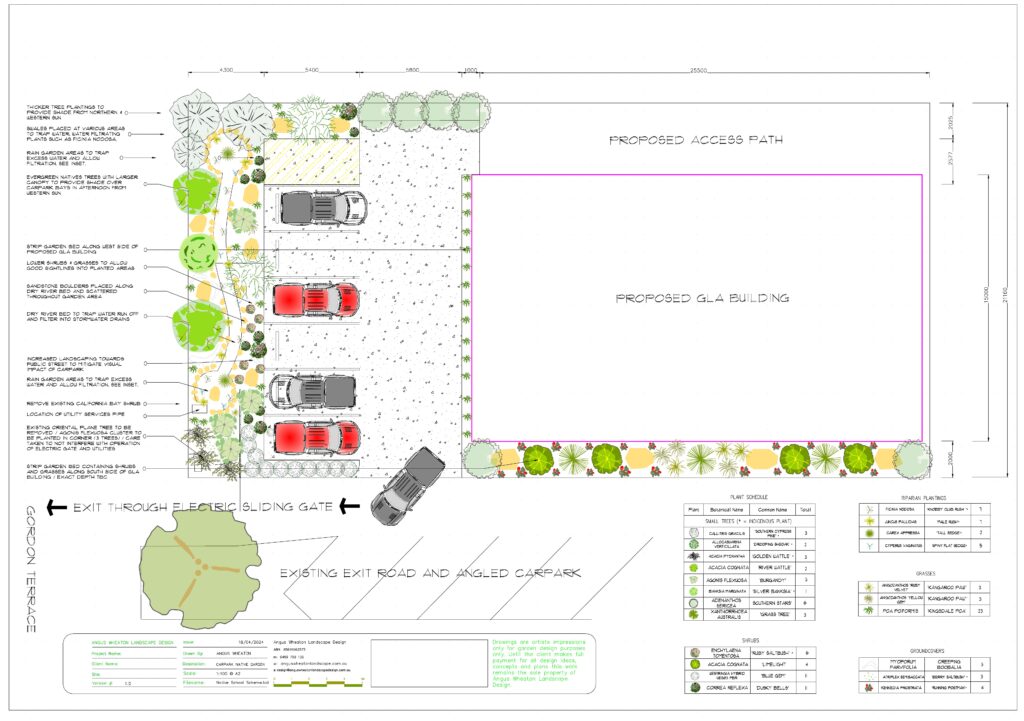
Here is an example of a PDF file generated using the SaveAsPDF tool. It is a page from a design by Angus Wheaton Landscape Design. Transparency (and gradients) have been applied to many entities in the design. Click the image to view the result as delivered to the client.
Development of the SaveAsPDF was initially prompted by inquiries from Mac users who wanted to print PDF output from their gCADPlus plans. At the time, there were no PDF writers available for the Mac. Printing PDF using various PDF writers such as CutePDF, Bullzip and Microsoft PDF leaves entities with no color or causes color bleed.
The figure below shows another example of a design printed this way using Save to PDF.
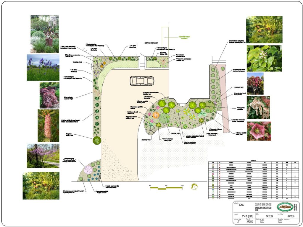
![]() The PDFSave command in gCADPlus generates a PDF file that shows transparency in planting symbols and other entities. Here we show a design for a revegetation project where the upper canopy symbols have transparency applied. This enables understory planting to show through in a PDF file.
The PDFSave command in gCADPlus generates a PDF file that shows transparency in planting symbols and other entities. Here we show a design for a revegetation project where the upper canopy symbols have transparency applied. This enables understory planting to show through in a PDF file.
The design space, as illustrated above, incorporates a scalebar. We added a rider that the construction team should not scale off distances from this print. We produce another print for the team that includes ‘proper’ dimensions
Tip: When generating PDF files this way, we suggest starting with a medium resolution setting that produces an acceptable result rather than selecting the maximum resolution. If you are working with a very detailed design, and choose maximum resolution, gCADPlus may print very slowly or even crash.
Some limitations of the SaveAsPDF feature.
A design cannot be printed to a fixed scale using this tool.
Fixed scale printing is done by highlighting (selecting) a floating viewport in a layout on a sheet size appropriate for your need, setting the scale, and printing 1:1. We use printers such as CutePDF, Bullzip, and PDFWriter. The figure below shows an example. The figure below shows a design ready for printing a design developed using decimal feet at a scale of 1/128. Since the design contains entities with transparency settings, the result will be unsatisfactory. If the client insists on a very high-resolution print to an accurate fixed scale, we edit those blocks and remove transparency.
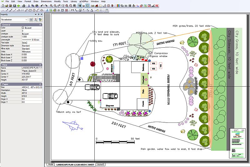
Tip: A tool on the Modify drop-down menu helps set the scale value when working in the USA Imperial system of units.
Tip: If we know in advance that our client insists on us producing a design printed to a fixed scale, we avoid transparency entirely.
More information on printing to fixed scales in the Imperial environment
![]() Using a design for a site in Washington State, USA, we show how to present the design at fixed scales on various architectural size sheets. We first test printing at a scale of 1″ to 128′ (1/128) and find that the lineweight is too heavy. In contrast, if the design was printed to a fixed scale of 1/32 on an architectural sheet using the same default lineweight settings, the lineweight of entities was appropriate. Finally, we show how to quickly and easily adjust the default lineweight value, ensuring that the line thickness is suitable no matter which sheet is used. We add internal checks by including a scale bar in modelspace and apply some key dimensions taken directly from the model.
Using a design for a site in Washington State, USA, we show how to present the design at fixed scales on various architectural size sheets. We first test printing at a scale of 1″ to 128′ (1/128) and find that the lineweight is too heavy. In contrast, if the design was printed to a fixed scale of 1/32 on an architectural sheet using the same default lineweight settings, the lineweight of entities was appropriate. Finally, we show how to quickly and easily adjust the default lineweight value, ensuring that the line thickness is suitable no matter which sheet is used. We add internal checks by including a scale bar in modelspace and apply some key dimensions taken directly from the model.
A related issue: apply gradients
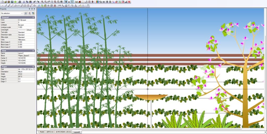
In gCADPlus, gradients can be applied to any closed and filled entity. Using gradient fills within closed polylines can increase vibrancy. Gradients can be point or linear types. The illustration below demonstrates a linear gradient [applied within a closed rectangle], serving as a sky backdrop for an elevation view of a courtyard design section.
Once the gradient has been applied, gCADPlus allows further editing with the choice of start color, end color, direction, and length of the gradient. These can be controlled via the properties box. The figure below shows petals in a symbol for Dianella revoluta have been given more subtlety by applying a point gradient.
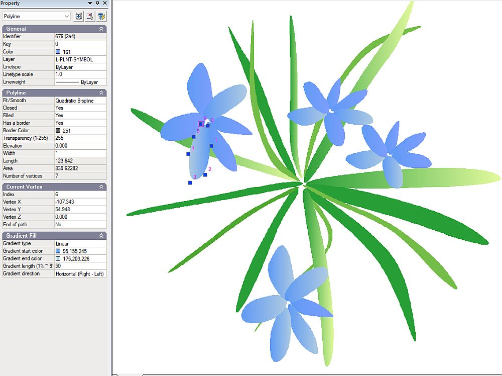
Note the start and end colors, and gradient direction can be set in the properties box.
![]() When creating plant symbols, it’s recommended to use gradients judiciously to avoid compromising performance, particularly during rapid zooming in on a design. Gradients should ideally be reserved for closed polylines such as those representing sections, lawns, pools, and wetlands.
When creating plant symbols, it’s recommended to use gradients judiciously to avoid compromising performance, particularly during rapid zooming in on a design. Gradients should ideally be reserved for closed polylines such as those representing sections, lawns, pools, and wetlands.
![]() This video addresses AngusW’s query on enhancing the effectiveness of symbols in elevation views with fill gradients. Initially, we introduce color to a birdbath’s elevation view, then proceed to a block representing Magnolia soulangeana. Both point and linear gradients are feasible within a filled polyline. We apply a gradient to the tree trunk, transitioning from a darker shade at the base to a lighter hue at the canopy’s tips. It’s important to note that employing gradients in landscape designs may lead to printing challenges at high resolutions with PDF writers. Should any part of the printout fail to render properly, consider lowering the PDF writer’s resolution.
This video addresses AngusW’s query on enhancing the effectiveness of symbols in elevation views with fill gradients. Initially, we introduce color to a birdbath’s elevation view, then proceed to a block representing Magnolia soulangeana. Both point and linear gradients are feasible within a filled polyline. We apply a gradient to the tree trunk, transitioning from a darker shade at the base to a lighter hue at the canopy’s tips. It’s important to note that employing gradients in landscape designs may lead to printing challenges at high resolutions with PDF writers. Should any part of the printout fail to render properly, consider lowering the PDF writer’s resolution.
Tip: A user in the UK [AP] has observed that gCADPlus’s performance significantly declines when new plant symbols have nested blocks with extensive use of the gradient tool.
Some comments on using transparency and gradients in landscape drawings.
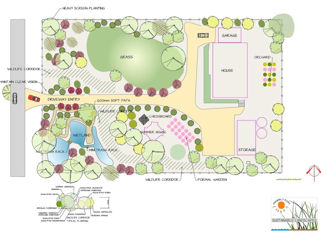
The design depicted in the figure below utilizes gradients for the wetlands and lawn areas, while transparency is applied selectively to allow visibility through an upper canopy to the understory planting beneath.
![]() We have been requested to produce a film that comments on our method of incorporating and utilizing transparency and gradients in our landscape design projects. While others may employ these techniques differently, our method is not the only definitive approach.
We have been requested to produce a film that comments on our method of incorporating and utilizing transparency and gradients in our landscape design projects. While others may employ these techniques differently, our method is not the only definitive approach.

