Learn CAD landscape software by copying a hand sketch
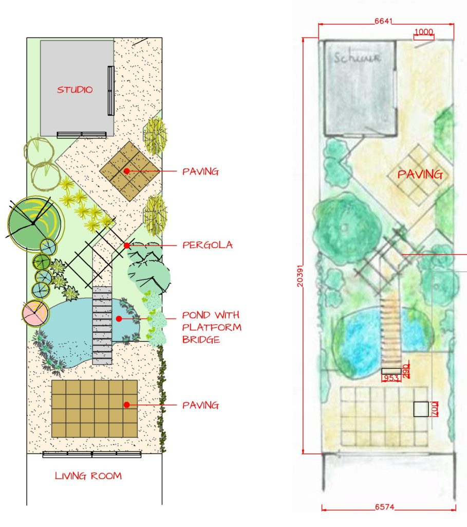
Here we learn CAD drafting by ‘recreating’ a hand-drawn sketch. This step-by-step guide uses the hand-drawn landscape plan shown below to recreate the design.

After playing the movie below, we suggest that you try this method on a design of your own. Since you have worked through and solved any site problem, the design for the garden (or larger space) is already set, so you can concentrate exclusively on learning to use of CAD commands. Do concentrate on the use of the draw and modifying commands.
Hand drawn sketch
![]() This video is designed to show shows how to take a hand-drawn landscape plan and recreate the design in CAD software. The garden space is small but crammed with interest. The line command is used to accurately define the site, the block command is used to create some large format pavers, a ‘bridge’ spans a small pond with riparian planting, a pergola is set at 45 degrees to the rectangular space, and so on.
This video is designed to show shows how to take a hand-drawn landscape plan and recreate the design in CAD software. The garden space is small but crammed with interest. The line command is used to accurately define the site, the block command is used to create some large format pavers, a ‘bridge’ spans a small pond with riparian planting, a pergola is set at 45 degrees to the rectangular space, and so on.
Download your free copy of gCADPlus.
Tips
When drafting by hand, it is usual to take a clean sheet of paper of appropriate size and put it on a drawing board (table) along with your scale ruler.
You then think about the design, the views, and scales that you will use to convey the design effectively, and finally put pen to paper, selecting drafting pens of varying thicknesses as you work. You work with a scale ruler all the time. The opposite is true when using CAD software. Everything you draw is full size.
![]() Sheets in Australia and Europe are usually the ISO A series – A0, A1. A2 etc. The B series of sheets – B1, B2, B3, and B4 – are less commonly used and are reserved for design work in the US.
Sheets in Australia and Europe are usually the ISO A series – A0, A1. A2 etc. The B series of sheets – B1, B2, B3, and B4 – are less commonly used and are reserved for design work in the US.
More about creating landscape plans with CAD software.
Key words: hand drafting, copy sketch, landscape cad software, hand drafting