Interpreting landscape plans is difficult, especially for clients. Elevation and section views of the design can help, but 3D views are often needed to convey design ideas. How best to do that?
Generating 3D views – hand sketch
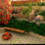
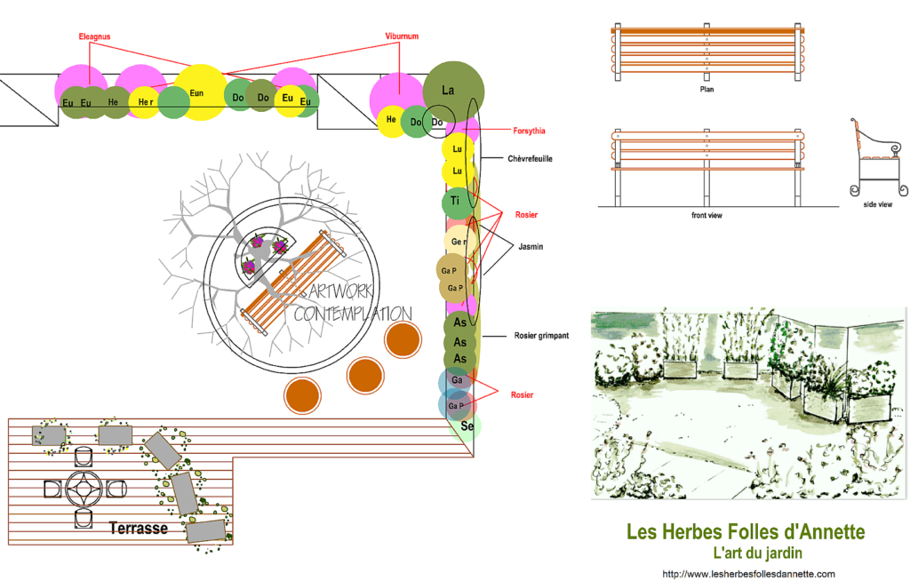
Some users hand sketch a 3d view and incorporate that into a set of gCADPlus plans as shown below. That technique is very efficient. Shown below – a quick hand sketch illustrates the arrangement of planter boxes on a terrace. Unfortunately, not everyone has the necessary skills or time to make these sketches.
The alternative – use 3D modeling software to generate a view
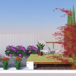
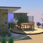
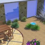
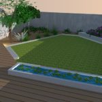
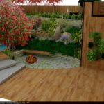
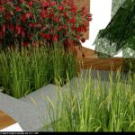
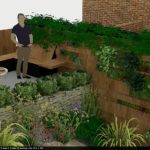
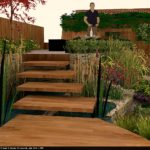
Rather than hand sketch, many designers export gCADPlus geometry to other software applications to build a computer-generated 3D representation of the design. Here are some examples of 3D landscape models generated in SketchUp from 2D designs created using gCADPlus.
Tip: SketchUp, a tool previously owned by Google and free to use, is now owned by Trimble. The professional version of SketchUp is relatively expensive at $USD 695.
It is possible to get information from gCADPlus to SketchUp easily because gCADPlus provides a convenient way of exporting base information from a 2D design and bringing it into SketchUp. Building a 3D model is then greatly simplified because the accurate 2D information from gCADPlus serves as a base for the 3D model.
You have three options for building a 3D model in SketchUp based on 2D information from gCADPlus:
- Export a graphic and use the free SketchUp application to build a model based on the graphic,
- Export a DXF file from gCADPlus and import into free SketchUp (using a plug in to allow DXF importation),
- Use a SketchUp Pro which has the ability to import both DXF and AutoCAD DWG files.
Option 1
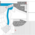
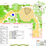
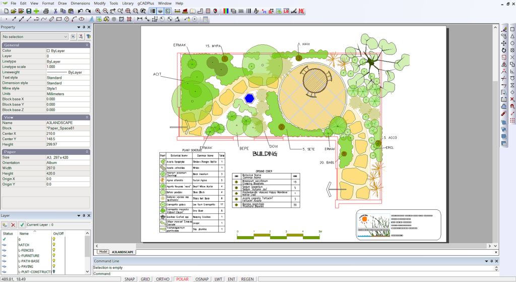
Take a gCADPlus drawing for an area new the side of a house as shown below.
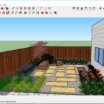
Move it to SketchUp and create the model.
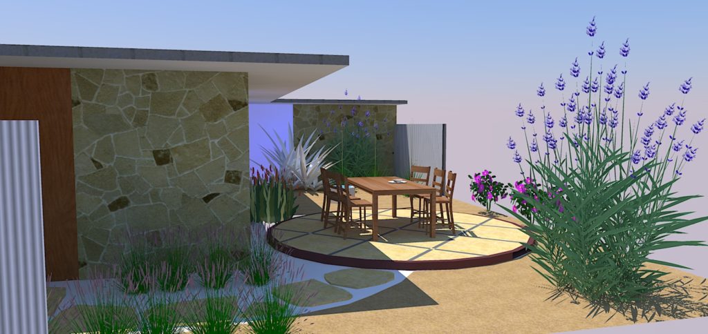
![]() Export a graphic image from gCADPlus and use it in SketchUp as a base for building a 3D model.
Export a graphic image from gCADPlus and use it in SketchUp as a base for building a 3D model.
Tip: For best results in SketchUp, export a view from layout space in .TIFF format.
Option 2 and 3
It is possible to assign a Z value to entities (structural elements) in the gCADPlus drawing. Use the “Create SketchUp Layers” tool and export accurate 2D information from gCADPlus in the form of a DXF file.
Place the file in SketchUp and build the model directly on the transferred information.
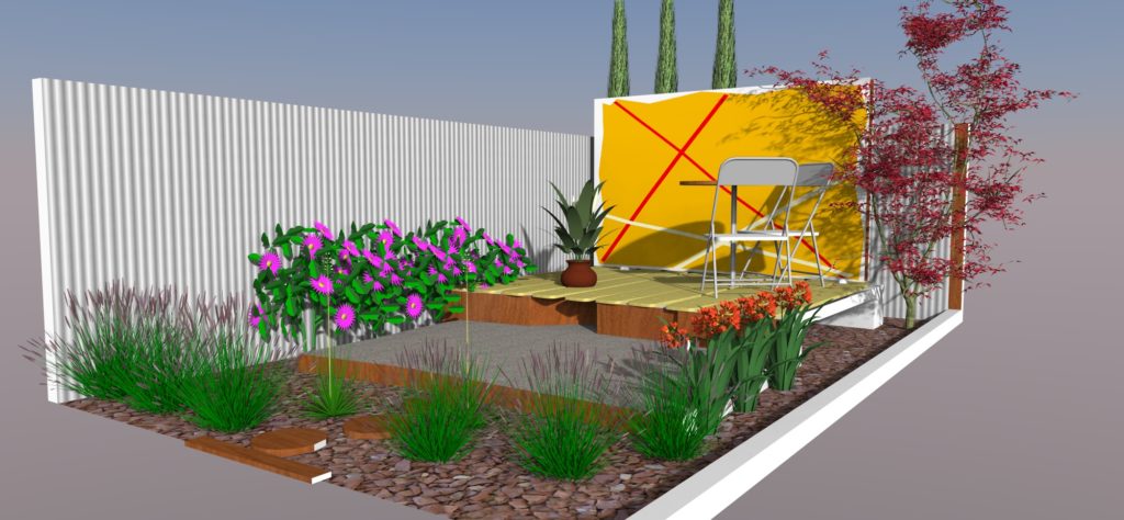
![]() Exporting geometry from gCADPlus as a DXF file, import it to SketchUp and begin building the model.
Exporting geometry from gCADPlus as a DXF file, import it to SketchUp and begin building the model.
Some tips on assigning Z values in the gCADPlus environment
Use the layer stack tool and isolate just those entities that you want to work with as a base in the SketchUp environment (turn off unwanted layers, including the layer on which plant symbols have been placed).
Select the Make SketchUp layers tool from the gCADPlus drop down menu.
Assign a Z coordinate to entities if required. In the example above, the yellow deck was set at 300, the grey paved area 100 and the white decoration 105.
Select entities (no hatching, no plant symbols, explode blocks if used to make structural details).
Hit Enter.
Choose whether or not to transfer symbols and text to another layer.
Start SketchUp and import the DXF file that’s been exported from gCADPlus. If you have assigned elevation values to each structural entity, it is a simple task to use the Push/Pull tool to create 3D geometry.
Use your SketchUp skills to assign materials to surfaces.
Add planting and furniture.
Adding textures.
If required, the model can be passed to rendering software for higher resolution and softening. Note the loss of detail of graphic on the screen wall. This is a function of the renderer in use. It is possible to include the graphic on the rear wall in some ray tracing software.
Some clients may benefit from seeing an animation of the proposed design.
